750W Bafang Mid Drive Installation
Getting started
Fitting a mid-drive unit is not for the inexperienced, the mid drive kit is a more difficult proposition. For a start you need some specialist tools which you can buy with your kit.
It’s also a lot easier if you have somebody to help you install who has done it all before, and I will confess that my friend Rohan and I who helped install Vik’s kit had already installed a BBS02 on Rohan’s own bike prior to this install. Rohan also has a bike workstand which makes the job easier and faster.
We knew what to expect, but that didn’t mean we had everything in the bag, because every bike is different. If you have friends to help who, like us enjoy a good beer, bring some along and you’re in good stead to have the job done well.
Here’s a list of the tools you will need
- Crank puller: this allows you to remove your existing cranks
- Crank allen key: 8mm
- Bottom bracket removal tool: this allows you to pull out your existing bottom bracket
- Bottom bracket tightener: this allows you to fit the first ring in the kit to attach the new bottom bracket, you can use a screwdriver and hammer to do this but it’s not recommended.
- Outer lock ring tool: this allows you to lock down the bottom bracket
- You will also need regular allen keys for removing and replacing the brake levers and installing the controls.
Away we go!
Let’s first look at the donor bike, the last thing you want when installing a kit of any kind, let alone a kit of 750w that will take you to 45km/h with no trouble, is a rubbish bike. Our donor is a bike that was near $1000 when new, the 2002 year model Marin Pallisades, a quality hard tail mountain bike with a solid frame and a good component mix. It has v-brakes on both ends but also has the ability to upgrade to a front disc which is a recommended upgrade for a 750w kit.
Crank and bottom bracket removal
This is usually the hardest part of the whole job! First of all you need to use your crank puller to get the old cranks off. It’s a good idea to remove the pedals while the crank is still on the bike, which we forgot to do.
Next is bottom bracket removal. You’ll need the bottom bracket removal tool for this, if you don’t have it you can stop right there as it is impossible to remove without the tool. In the image below you will see that we placed a flat spanner (1) on the spindle of the bottom bracket with the splined removal tool (2) using the crank bolt (3) holding it in place. This prevents the splined tool from slipping out. Some tips for removal:
- First remove the left hand side splined lock ring, as you won’t be able to undo the right hand side with the left still installed. The left thread is standard, you undo it counter clockwise
- Second remove the right hand side, which is a reverse thread so you undo it clockwise

Remove derailleur, install controls
OK, it’s out! The next thing we did was remove the front derailleur and fit the controls on the handlebars. There is no need for your front derailleur anymore, so unbolt the lot and remove the shifter, cable and derailleur.

To remove the shifter, you’ll need to take off your handlebar grip (we used methylated spirit on a thin allen key inserted under the grip) and remove the brake lever. You’ll have new e-bike cut off levers to install on both sides so remove both grips.

Your LCD display will slip over the handle bars but if you have bars with a thicker section at the middle where the display mounts, you might need to cut the rubber shims which come with the kit in half and install some thinner rubber to be able to install the bolts and nuts which hold it tightly on the handlebar.

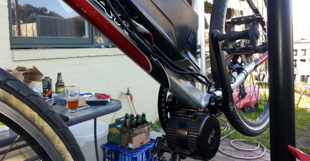
Install the mid drive motor assembly
The unit should just slip in, however there are a few variables depending on your bike. The Marin has a cable guide underneath the bottom bracket, it’s held in by a screw and in this case the head of the screw was too tall for the motor to clear it. We had to find a flatter screw which allowed the motor to fit, luckily we had a screw with the same thread as the stock one but with a flat head. Once you slide the bottom bracket and motor through from the drive side, place the flat holding plate over the bottom bracket, and install the first lock ring (1) shown in the picture below. A standard old style bottom bracket lock ring tool, or screwdriver and hammer will do the job, we luckily had the former on hand. Then install the two bolts that hold the motor in place, ensuring the motor is rotated forward as shown below.

We also found that we needed a couple of washers on the bolts that secure the unit to the left hand non drive side of the bottom bracket to get perfect alignment for the width of our bottom bracket, you may or may not need this. Once that is all tightened up, install the outer lock ring, this requires a special tool which you can obtain from your local bike shop.
Now it’s time to install the chaingring with the supplied 5 bolts. The bump on the chainring faces out as shown so that the chain line is correct.


Then place the chain on the chainring and from the opposite side, and install the chain guard with the supplied screws.

Step 4, battery holder, sensors, cranks and wiring
We then installed the battery holder, it simply bolts on to the bottle cage mounts on your bike.

The kit comes with a speed sensor which mounts on to the back wheel and plugs into the appropriate wire coming from the motor, it is just like a regular bike speedometer sensor and should be mounted on the left chainstay (so as not to get caught up in the chain) by pressing the adhesive patch into position and cable tying. Ensure that the magnet which mounts on the spoke is aligned correctly as shown.

Install the cranks, and if you like have a beer because you are nearly there!

Time to wire everything up, all the connectors except the bullet connectors for the battery have arrows on them to indicate the correct alignment, and the brake and throttle sensors are colour coded so you can’t go wrong. The speed sensor wire should be routed and secured so it stays away from your spinning wheel.


When it’s all wired up, install the battery, ensuring it is turned off before you do, and then get ready to test the system. At this point have a think about some conduit or spiral cable tube to keep it all neat, and cable tie everything to keep it secure. We didn’t have a spiral tube on the day but it will be installed later.

Now switch on the battery, and switch on the system by holding the power button (middle button on the PAS/Power control) down for a few seconds. The LCD display will come on, and if it all looks normal (showing 0km/h and pedal assist 1) you’re ready to go, crank the pedals a couple of times and the system will kick in and turn the wheel.